OMDW — DUBAI / AL MAKTOUM INTERNATIONAL
Note: The following sections in this chapter are intentionally left blank:AD 2.21.
OMDW AD 2.1 AERODROME LOCATION INDICATOR AND NAME
OMDW — DUBAI / AL MAKTOUM INTERNATIONAL
OMDW AD 2.2 AERODROME GEOGRAPHICAL AND ADMINISTRATIVE DATA
| 1 | ARP coordinates and site at AD | 245506N 0551032E At centre of existing and future RWYs, perpendicular to midpoint of RWY 12 / 30 | ||||||||||||||
| 2 | Direction and distance from (city) | 20 NM SW of Dubai city | ||||||||||||||
| 3 | Elevation/Reference temperature | 171 FT / 44° C | ||||||||||||||
| 4 | Geoid undulation at AD ELEV PSN | -112 FT | ||||||||||||||
| 5 | MAG VAR/Annual change | 2° E (2020) / 0.05° E | ||||||||||||||
| 6 | AD Administration, address, telephone, telefax, telex, AFS |
| ||||||||||||||
| 7 | Types of traffic permitted (IFR/VFR) | IFR / VFR | ||||||||||||||
| 8 | Remarks | OMDW operates as a IATA level 2 slot coordinated airport. No operator shall operate to or from OMDW without first obtaining clearance from Airport Coordination Limited (ACL) and subject to landing permission from the DCAA. Schedules should be sent in IATA SSIM format to ACL in the time scales specified by the IATA schedules calendar to the address below. Email: slots@acl-international.com FAX: +44 (0) 208 564 0691 Aircraft greater in size than ICAO Code F (Wingspan Greater than 80 M) must provide 72 hour advance notice to the aerodrome in addition to a slot request to ACL. Email: Safeguarding-aim@dubaiairports.ae EFTA operates to the South of OMDW RWY 12/30. EFTA RWY 13/31 is not available for commercial aircraft. Operators are to be aware of high intensity training activities in this area. |
OMDW AD 2.3 OPERATIONAL HOURS
| 1 | AD Administration | H24 |
| 2 | Customs and immigration | H24 |
| 3 | Health and sanitation | H24 |
| 4 | AIS Briefing Office | H24 |
| 5 | ATS Reporting Office (ARO) | H24 |
| 6 | MET Briefing Office | H24 |
| 7 | ATS | H24 |
| 8 | Fuelling | H24 |
| 9 | Handling | H24 |
| 10 | Security | H24 |
| 11 | De-icing | NIL |
| 12 | Remarks | Prior approval required from EFTA Operations for non-EFTA flights. EFTA operates as per the below timings: 01 JAN – 31 MAY 0400 – 2000 UTC 01 JUN – 30 SEP 0200 – 1000 UTC and 1200 – 2000 UTC 01 OCT – 31 DEC 0300 – 1900 UTC Note: There will be no flying outside the above timings. |
OMDW AD 2.4 HANDLING SERVICES AND FACILITIES
| 1 | Cargo-handling facilities | Complete semi - automatic facilities |
| 2 | Fuel/oil types | Jet A1: Emojet, ENOC, Shell, Air BP, Total, Chevron Note: Chevron fuel must be arranged in advance. H24 telephone +971 50 5526 712 Oil: All grades |
| 3 | Fuelling facilities/capacity | Hydrant fuelling S804 EFTA: 11E EFTA Limited bowser service also |
| 4 | De-icing facilities | NIL |
| 5 | Hangar space for visiting aircraft | NIL |
| 6 | Repair facilities for visiting aircraft | Limited available on request |
| 7 | Remarks | NIL |
OMDW AD 2.5 PASSENGER FACILITIES
| 1 | Hotels | Hotel accommodation available in Dubai City and Jebel Ali |
| 2 | Restaurants | H24 |
| 3 | Transportation | Taxis, buses and rental cars. |
| 4 | Medical facilities | Medical Centre at airport. Emirates Medical Centre (EFTA only). Hospitals in Dubai City and Jebel Ali. |
| 5 | Bank and Post Office | ATM available, Post Office N/A |
| 6 | Tourist Office | NIL |
| 7 | Remarks | Limited |
OMDW AD 2.6 RESCUE AND FIRE FIGHTING SERVICES
| 1 | AD category for fire fighting | CAT 9 (CAT 10 on request). EFTA: CAT 3. |
| 2 | Rescue equipment | Rescue & Firefighting Vehicles:
|
| 3 | Capability for removal of disabled aircraft | Lifting and hydraulic jacks supplied through SLA (Service Level Agreement) with Emirates Airlines for aircraft sizes upto and including A380, 2 stored in the Main Fire Station (Airside) |
| 4 | Remarks | NIL |
OMDW AD 2.7 SEASONAL AVAILABILITY - CLEARING
| 1 | Types of clearing equipment | NIL |
| 2 | Clearance priorities | NIL |
| 3 | Remarks | Aerodrome is available all season. There is no requirement for clearing. |
OMDW AD 2.8 APRONS, TAXIWAYS AND CHECK LOCATIONS/POSITIONS DATA
| 1 | Apron surface and strength | |
| 2 | Taxiway width, surface and strength | |
| 3 | Altimeter checkpoint location and elevation | Individual |
| 4 | VOR checkpoints | NIL |
| 5 | INS checkpoints | see Parking /Docking Charts |
| 6 | Remarks | Aircraft Code Restrictions / Engines Runs / Compass Swing
|
Aircraft Turns:
| ||
Wingtip Clearance:
|
| Apron Designation | Surface | PCN | Notes |
|---|---|---|---|
Aprons Restrictions:
| |||
| Table 1: Apron details | |||
| S2 | Concrete | 72/R/B/W/T | |
| S3 | Concrete | 90/R/A/W/T | Stands H1, |
| S4 | Concrete | 90/R/A/W/T | |
| S8 | Concrete | 90/R/A/W/T | |
| G (1-20) | Concrete | 62/R/B/W/T | G10-G11; G14-G15 and G17-G20 box stands |
| G (100-103) | Concrete | 86/R/B/W/T | Box stands |
| APRON 1 | Interlock paving | 6/R/B/Y/T | Aircraft can park on each stand either east or west. |
| APRON 2 | Interlock paving | 6/R/B/Y/T | Aircraft can park on each stand either east or west. |
| APRON 3 | Interlock paving | 6/R/B/Y/T | Aircraft can park on each stand either east or west. |
| APRON 4 | Interlock paving | 6/R/B/Y/T | Aircraft can park on each stand either east or west. |
| APRON 5 | Interlock paving | 6/R/B/Y/T | Aircraft can park on each stand either east or west. |
| Designation | ICAO Code | Length (M)(1) | Width (M) | Shoulder either side (M) | Strip (M) (minimum) | Surface | PCN |
|---|---|---|---|---|---|---|---|
| ** Crossover Taxiway | |||||||
| (1) Calculated Values | |||||||
Taxiways Restrictions:
| |||||||
| Table 2: Taxiway details | |||||||
| TWY U | F | 424 | 25 | 18 | 115 | Asphalt | 140/F/A/X/T |
| TWY U4 | F | 765 | 25 | 18 | 115 | Asphalt | 140/F/A/X/T |
| TWY V | F | 4526 | 25 | 18 | 115 | Asphalt | 140/F/A/X/T |
| F | 25 | 18 | 115 | Concrete | 120/R/A/W/T | ||
| TWY V1 | F | 200 | 25 | 18 | 115 | Asphalt | 140/F/A/X/T |
| F | 83 | 25 | 18 | 115 | Concrete | 120/R/A/W/T | |
| TWY V2 | F | 202 | 30 | 18 | 115 | Asphalt | 140/F/A/X/T |
| F | 84 | 30 | 18 | 115 | Concrete | 120/R/A/W/T | |
| TWY V3 | F | 204 | 30 | 18 | 115 | Asphalt | 140/F/A/X/T |
| F | 84 | 30 | 18 | 115 | Concrete | 120/R/A/W/T | |
| TWY V4 | F | 203 | 30 | 18 | 115 | Asphalt | 140/F/A/X/T |
| F | 84 | 30 | 18 | 115 | Concrete | 120/R/A/W/T | |
| TWY V6 | F | 566 | 25 | 18 | 115 | Asphalt | 140/F/A/X/T |
| TWY V7 | F | 571 | 25 | 18 | 115 | Asphalt | 140/F/A/X/T |
| TWY V8 | F | 568 | 25 | 18 | 115 | Asphalt | 140/F/A/X/T |
| TWY V9 | F | 570 | 25 | 18 | 115 | Asphalt | 140/F/A/X/T |
| TWY V10 | F | 449 | 25 | 18 | 115 | Asphalt | 140/F/A/X/T |
| TWY V11 | F | 567 | 25 | 18 | 115 | Asphalt | 140/F/A/X/T |
| TWY V12 | F | 568 | 25 | 18 | 115 | Asphalt | 140/F/A/X/T |
| TWY V13 | F | 560 | 25 | 18 | 115 | Asphalt | 140/F/A/X/T |
| TWY V16 | F | 246 | 30 | 18 | 115 | Asphalt | 140/F/A/X/T |
| F | 30 | 18 | 115 | Concrete | 120/R/A/W/T | ||
| TWY V17 | F | 289 | 30 | 18 | 115 | Asphalt | 140/F/A/X/T |
| F | 30 | 18 | 115 | Concrete | 120/R/A/W/T | ||
| TWY V18 | F | 286 | 30 | 18 | 115 | Asphalt | 140/F/A/X/T |
| F | 30 | 18 | 115 | Concrete | 120/R/A/W/T | ||
| TWY V19 | F | 285 | 30 | 18 | 115 | Asphalt | 140/F/A/X/T |
| F | 30 | 18 | 115 | Concrete | 120/R/A/W/T | ||
| TWY V20 | F | 283 | 30 | 18 | 115 | Asphalt | 140/F/A/X/T |
| F | 30 | 18 | 115 | Concrete | 120/R/A/W/T | ||
| TWY V21 | F | 285 | 25 | 18 | 115 | Asphalt | 140/F/A/X/T |
| F | 25 | 18 | 115 | Concrete | 120/R/A/W/T | ||
| TWY W | F | 4526 | 25 | 18 | 115 | Asphalt | 140/F/A/X/T |
| F | 25 | 18 | 115 | Concrete | 120/R/B/W/T | ||
| TWY W1 | F | 100 | 25 | 18 | 115 | Concrete | 140/R/B/W/T |
| TWY W2 | F | 100 | 55 | 18 | 115 | Concrete | 140/R/B/W/T |
| TWY W4 | F | 100 | 54 | 18 | 115 | Concrete | 140/R/B/W/T |
| TWY W7 | F | 413 | 25 | 18 | 115 | Asphalt | 140/F/A/X/T |
| TWY W8 | F | 412 | 25 | 18 | 115 | Asphalt | 140/F/A/X/T |
| TWY W9 | F | 100 | 54 | 18 | 115 | Asphalt | 140/F/A/X/T |
| TWY W10 | F | 413 | 25 | 18 | 115 | Asphalt | 140/F/A/X/T |
| TWY W11 | F | 413 | 25 | 18 | 115 | Asphalt | 140/F/A/X/T |
| TWY W12 | F | 100 | 54 | 18 | 115 | Asphalt | 140/F/A/X/T |
| TWY W13 | F | 100 | 54 | 18 | 115 | Asphalt | 140/F/A/X/T |
| TWY W14 | F | 413 | 25 | 18 | 115 | Asphalt | 140/F/A/X/T |
| TWY W15 | F | 413 | 25 | 18 | 115 | Asphalt | 140/F/A/X/T |
| TWY W16 | F | 184 | 25 | 18 | 115 | Asphalt | 140/F/A/X/T |
| F | 228 | 25 | 18 | 115 | Concrete | 140/R/A/W/T | |
| TWY W17 | F | 185 | 37 | 18 | 115 | Asphalt | 140/F/A/X/T |
| F | 228 | 37 | 18 | 115 | Concrete | 140/R/A/W/T | |
| TWY W18 | F | 84 | 38 | 18 | 115 | Asphalt | 140/F/A/X/T |
| F | 229 | 38 | 18 | 115 | Concrete | 140/R/A/W/T | |
| TWY W19 | F | 313 | 37 | 18 | 115 | Concrete | 140/R/A/W/T |
| TWY W20 | F | 313 | 37 | 18 | 115 | Concrete | 140/R/A/W/T |
| TWY W21 | F | 413 | 25 | 18 | 115 | Concrete | 140/R/A/W/T |
| TWY Z | F | 4544 | 25 | 18 | 115 | Asphalt | 140/F/A/X/T |
| F | 25 | 18 | 115 | Concrete | 90/R/A/W/T | ||
| TXL Z5 | F | 1213 | 25 | Concrete | 72/R/B/W/T | ||
| TXL Z6 | F | 1213 | 25 | Concrete | 90/R/A/W/T | ||
| TXL Z7 | F | 1212 | 25 | Concrete | 90/R/A/W/T | ||
| TXL Z8 | F | 1213 | 25 | Concrete | 90/R/A/W/T | ||
| TXL Z9 | C | 872 | 18 | Concrete | 86/R/B/W/T | ||
| TXL Z10 | C | 872 | 18 | Concrete | 86/R/B/W/T | ||
| TXL Z11 | F | 1514 | 25 | Concrete | 86/R/B/W/T | ||
| TXL Z12 | F | 1525 | 25 | Asphalt | 71/F/B/W/T | ||
| TXL Z13 | C | 443 | 18 | Asphalt | 55/F/B/W/T | ||
| TXL Z14 | C | 542 | 18 | Asphalt | 55/F/B/W/T | ||
| TXL Z15 | C | 573 | 18 | Asphalt | 55/F/B/W/T | ||
| TXL Z16 | C | 432 | 31 | Asphalt | 55/F/B/W/T | ||
| TXL Z17 | C | 432 | 31 | Asphalt | 55/F/B/W/T | ||
| TXL Z20 | C | 573 | 18 | Asphalt | 55/F/B/W/T | ||
| TXL Z21 | F | 100 | 54 | Concrete | 86/R/B/W/T | ||
| TXL Z22 | F | 100 | 54 | Concrete | 86/R/B/W/T | ||
| TXL Z23 | F | 100 | 54 | Concrete | 86/R/B/W/T | ||
| TXL Z24 | F | 100 | 26 | Concrete | 86/R/B/W/T | ||
| TWY Z51** | F | 312 | 25 | 18 | Concrete | 72/R/B/W/T | |
| TWY Z52** | F | 312 | 25 | 18 | Concrete | 72/R/B/W/T | |
| TWY Z53** | F | 315 | 25 | 18 | Concrete | 72/R/B/W/T | |
| TWY Z54** | F | 315 | 25 | 18 | Concrete | 72/R/B/W/T | |
| TWY Z71** | F | 308 | 25 | 18 | Concrete | 90/R/B/W/T | |
| TWY Z72** | F | 308 | 25 | 18 | Concrete | 90/R/B/W/T | |
| TWY Z73** | F | 308 | 25 | 18 | Concrete | 90/R/B/W/T | |
| TWY Z74** | F | 308 | 25 | 18 | Concrete | 90/R/B/W/T | |
| TWY Z91** | C | 187 | 18 | 4 | Concrete | 86/R/B/W/T | |
| TWY Z92** | C | 185 | 18 | 4 | Concrete | 86/R/B/W/T | |
| TWY A | B | 1827 | 10 | N/A | 40 | Asphalt | 6/F/B/Y/T |
| TWY A1 | B | 121 | 10 | N/A | 31 | Asphalt | 6/F/B/Y/T |
| TWY A2 | B | 118 | 11 | N/A | 31 | Asphalt | 6/F/B/Y/T |
| TWY A3 | B | 201 | 11 | N/A | 40 | Asphalt | 6/F/B/Y/T |
| TWY A4 | B | 104 | 12 | N/A | 40 | Asphalt | 6/F/B/Y/T |
| TWY A5 | B | 201 | 11 | N/A | 40 | Asphalt | 6/F/B/Y/T |
| TWY A6 | B | 120 | 11 | N/A | 31 | Asphalt | 6/F/B/Y/T |
| TWY A7 | B | 120 | 10 | N/A | 31 | Asphalt | 6/F/B/Y/T |
| TWY Z12S | A | 253 | 11 | N/A | 31 | Asphalt | 6/F/B/Y/T |
| TXL L1 | B | 116 | 24 | N/A | Interlock paving | 6/R/B/Y/T | |
| TXL L2 | B | 116 | 27 | N/A | Interlock paving | 6/R/B/Y/T | |
| TXL L3 | B | 116 | 34 | N/A | Interlock paving | 6/R/B/Y/T | |
| TXL L4 | B | 116 | 25 | N/A | Interlock paving | 6/R/B/Y/T | |
| TXL L5 | B | 131 | 32 | N/A | Interlock paving | 6/R/B/Y/T | |
| TXL L6 | B | 116 | 24 | N/A | Interlock paving | 6/R/B/Y/T | |
| Designation | Turn Restrictions | |
|---|---|---|
| Table 3: Taxiway Turn Restrictions | ||
| TWY V4 | Heading South right turn onto TWY V not AVBL | |
| TWY V6 | Heading West left turn onto TWY V not AVBL | |
| TWY V7 | Heading East right turn onto TWY V not AVBL | |
| TWY V8 | Heading West left turn onto TWY V not AVBL | |
| TWY V9 | Heading East right turn onto TWY V not AVBL | |
| TWY V10 | Heading West left turn onto TWY V not AVBL | |
| TWY V11 | Heading East right turn onto TWY V not AVBL | |
| TWY V12 | Heading West left turn onto TWY V not AVBL | |
| TWY V13 | Heading East right turn onto TWY V not AVBL | |
| TWY W17 | Heading North left turn onto TWY W not AVBL | |
| Heading North left/right turns onto TWY V not AVBL | ||
| Heading South left turn onto TWY W not AVBL | ||
OMDW AD 2.9 SURFACE MOVEMENT GUIDANCE AND CONTROL SYSTEM AND MARKINGS
| 1 | Use of aircraft stand ID signs, TWY guide lines and visual docking/parking guidance system of aircraft stands | See OMDW AD 2.23.3 |
| 2 | RWY and TWY markings and lights | RWY 12/30 markings: Full ICAO runway designation, side stripes, pre-THR, transverse stripe, CL, TDZ, aiming point. RWY 13/31 markings: Full ICAO runway designation, side stripes, displaced THR, transverse stripe, CL, TDZ, aiming point. TWY markings: continuous yellow CL, double yellow edge lines and transverse yellow striping on corners and curves, excluding TWY A, TWY A1, TWY A2, TWY A3, TWY A4, TWY A5, TWY A6, TWY A7 and TWY Z12S no transverse striping on corners and curves. CAT II / III holding positions: Yellow pattern B CAT I holding positions: Yellow Pattern A IHP markings: Dashed Yellow TWY LGT: LIH yellow RETIL with 2 M lateral spacing at distances of 300 M (3 lights), 200 M (2 lights) and 100 M (1 light) from the RET point of tangency. |
| 3 | Stop bars and runway guard lights | Stop bar LGT: Variable intensity red uni-directional inset with additional pair of elevated edge lights are located at all lead-in TWYs and linked to intrusion sensor for RWY. RWY guard LGT: RWY holding positions are provided with a pair of yellow flashing lights on either side of the Stop bar. IHP LGT: A set of three variable intensity yellow inset lights are provided at all intermediate TWY holding positions. |
| 4 | Remarks | NIL |
OMDW AD 2.10 AERODROME OBSTACLES
To acquire Area 2 electronic obstacle data, contact details are available in GEN 3.1.6
Electronic obstacle data for Area 3 are not available.
| In approach/TKOF areas | |||||
|---|---|---|---|---|---|
| Obstacle ID / Designation | Obstacle type | Obstacle Position | Elevation (FT) Height (FT) | Markings Lighting Type / Colour | Remarks |
| OMDW 6183 / 30_LOC_FFM | NAVAID | 245304.6N 0551058.1E | 183 16 | Yes NIL / NIL | 12 TOCS |
| OMDW 2872 / 30_LOC | NAVAID | 245431.4N 0550822.8E | 125 14 | Yes STD / RED | 30 TOCS |
| OMDW 2873 / 30_LOC | NAVAID | 245430.1N 0550821.9E | 125 14 | Yes STD / RED | 30 TOCS |
| OMDW 6195 / 12_LOC_FFM | NAVAID | 245431.0N 0550821.9E | 126 15 | Yes NIL / NIL | 30 TOCS |
| OMDW 2887 / APPROACH_LIGHT | NAVAID | 245141.9N 0551007.6E | 162 3 | No NIL / NIL | 13 TOCS |
| OMDW 2890 / APPROACH_LIGHT | NAVAID | 245216.1N 0550905.9E | 162 16 | No NIL / NIL | 31 TOCS |
| OMDW 16136 / 31_LOC_NFM | NAVAID | 245215.8N 0550906.4E | 161 6 | Yes NIL / NIL | 31 TOCS |
| In circling area and at AD | |||||
|---|---|---|---|---|---|
| Obstacle ID / Designation | Obstacle type | Obstacle Position | Elevation (FT) Height (FT) | Markings Lighting Type/Colour | Remarks |
| OMDW AD 2713 / ATC_TOWER_AERIAL | BUILDING | 245320.0N 0550926.2E | 443 310 | Yes STD / RED | NIL |
| OMDW AD 6184 / 12_GP_MAST | NAVAID | 245424.0N 0550842.9E | 172 59 | Yes STD / RED | NIL |
| OMDW AD 6196 / 30_GP_MAST | NAVAID | 245319.0N 0551040.4E | 221 59 | Yes STD / RED | NIL |
| OMDW AD 2574 / 31_GP_MAST | NAVAID | 245154.3N 0550953.4E | 207 53 | Yes STD / RED | NIL |
| OMDW AD 2585 / TOWER_AERIAL | BUILDING | 245203.4N 0550944.2E | 229 71 | Yes NIL / NIL | NIL |
| OMDW AD 2589 / FLOODLIGHT | POLE | 245204.2N 0550942.8E | 229 73 | No STD / RED | NIL |
| OMDW AD 8875 / WINDSLEEVE | NAVAID | 245209.7N 0550923.0E | 174 20 | Yes STD / RED | NIL |
| OMDW AD 8876 / WINDSLEEVE | NAVAID | 245146.1N 0550954.5E | 171 20 | Yes STD / RED | NIL |
| OMDW AD 8877 / MET_MAST | NAVAID | 245208.8N 0550923.8E | 187 35 | No STD / RED | NIL |
| OMDW AD 8879 / MET_MAST | NAVAID | 245154.0N 0550950.9E | 190 33 | No STD / RED | NIL |
OMDW AD 2.11 METEOROLOGICAL INFORMATION PROVIDED
| 1 | Associated MET Office | Dubai MET | ||||
| 2 | Hours of service MET Office outside hours | H24 NIL | ||||
| 3 | Office responsible for TAF preparation Periods of validity | Dubai MET 30 HR, issued every 6 HR | ||||
| 4 | Trend forecast and Interval of issuance | TREND H24, issued every 1/2 HR | ||||
| 5 | Briefing/consultation provided | T, D Internet | ||||
| 6 | Flight documentation Language(s) used | C, TB English | ||||
| 7 | Charts and other information available for briefing or consultation | P 50 - 450 , SWH, SWM, SWL | ||||
| 8 | Supplementary equipment available for providing information | Satellite Imagery, Weather Radar | ||||
| 9 | ATS units provided with information | OMDW | ||||
| 10 | Additional information (limitation of service, etc.) |
| ||||
| Abbreviations (from Doc 8126) P = Personal, T = Telephone, D = Self-Briefing Display, C = Charts, TB = Tabular Data, P50 - 450 = Prognostic Upper Air Chart FL50-FL450, SWH = Significant Weather High (Chart), SWM = Significant Weather Medium (Chart), SWL = Significant Weather Low (Chart) Internet: www.avmet.ae - Registration required | ||||||
| Mean daily maximum and minimum temperatures (˚C) for each month of the year | ||||||||||||
|---|---|---|---|---|---|---|---|---|---|---|---|---|
| JAN | FEB | MAR | APR | MAY | JUN | JUL | AUG | SEP | OCT | NOV | DEC | |
| Maximum Minimum | 25 13 | 27 14 | 30 17 | 35 21 | 40 24 | 42 27 | 44 30 | 44 30 | 42 28 | 37 23 | 31 18 | 27 15 |
OMDW AD 2.12 RUNWAY PHYSICAL CHARACTERISTICS
| Designations RWY NR | TRUE & MAG BRG | Dimensions of RWY(M) | Strength (PCN) and surface of RWY and SWY | THR coordinates RWY end coordinates THR geoid undulation | THR elevation and highest elevation of TDZ of precision APP RWY |
|---|---|---|---|---|---|
| 1 | 2 | 3 | 4 | 5 | 6 |
| 12 | 121° / 119° | 4500 x 60 | 140/F/A/X/T Asphalt | 245425.74N 0550831.45E -111.5 FT | 115.2 FT 118.4 FT |
| 30 | 301° / 299° | 4500 x 60 | 140/F/A/X/T Asphalt | 245309.88N 0551048.54E -111.5 FT | 170.7 FT 170.7 FT |
| 13 | 121° / 119° | 1838 x 30 | 6/F/B/Y/T Asphalt | 245211.90N 0550913.41E -111.5 FT245143.45N 0551004.82E | 155.4 FT NIL |
| 31 | 301° / 299° | 1838 x 30 | 6/F/B/Y/T Asphalt | 245145.98N 0551000.25E -111.5 FT245214.43N 0550908.84E | 155.4 FT 155.0 FT |
| Slope of RWY-SWY | SWY dimensions (M) | CWY dimensions (M) | Strip dimensions (M) | RESA (M) | Arresting system | ||
|---|---|---|---|---|---|---|---|
| 7 | 8 | 9 | 10 | 11 | 12 | ||
| 12 | +0.11% (first 1762.5 M) +0.5% (next 2737.5 M) | NIL | NIL | NIL | * x 280 | 236 x 150 | Not Implemented |
| 30 | -0.5% (first 2737.5 M) -0.11% (next 1762.5 M) | NIL | NIL | NIL | * x 280 | 236 x 150 | |
| 13 | 0% | NIL | NIL | NIL | * x 140 | 120 x 80 | |
| 31 | NIL | NIL | NIL | * x 140 | 120 x 80 | ||
| Obstacle Free Zone | Remarks | |
|---|---|---|
| 13 | 14 | |
| 12 | Provided in compliance with UAE Civil Aviation Regulations, Part IX, 4.18 - SAFEGUARDING OF AERODROME SURROUNDINGS and in accordance with ICAO Annex 14, Chapter 4 Compliant with PANS-OPS Volume II |
|
| 30 | ||
| 13 | ||
| 31 | ||
OMDW AD 2.13 DECLARED DISTANCES
| RWY Designator | TORA (M) | TODA (M) | ASDA (M) | LDA (M) | Remarks |
|---|---|---|---|---|---|
| 1 | 2 | 3 | 4 | 5 | 6 |
| * No TORA sign. For EFTA base aircraft and helicopter departures only. | |||||
| 12 | 4500 | 4500 | 4500 | 4500 | NIL |
| 30 | 4500 | 4500 | 4500 | 4500 | NIL |
| 12 | 4452 | 4452 | 4452 | Take-off from V2 | |
| 12 | 4352 | 4352 | 4352 | Take-off from V3 | |
| 12 | 4252 | 4252 | 4252 | Take-off from V4 | |
| 12 | 3030 | 3030 | 3030 | Take-off from V6 | |
| 12 | 3030 | 3030 | 3030 | Take-off from U4 | |
| 12 | 2122 | 2122 | 2122 | Take-off from V10* | |
| 30 | 4390 | 4390 | 4390 | Take-off from V20 | |
| 30 | 4288 | 4288 | 4288 | Take-off from V19 | |
| 30 | 4188 | 4188 | 4188 | Take-off from V18 | |
| 30 | 4088 | 4088 | 4088 | Take-off from V17 | |
| 30 | 3995 | 3995 | 3995 | Take-off from V16 | |
| 30 | 2980 | 2980 | 2980 | Take-off from V13 | |
| 30 | 1622 | 1622 | 1622 | Take-off from V7* | |
| 13 | 1838 | 1838 | 1838 | 1688 | EFTA |
| 31 | 1838 | 1838 | 1838 | 1688 | EFTA |
| 13 | 1804 | 1804 | 1804 | Take-off from A2 EFTA | |
| 31 | 1804 | 1804 | 1804 | Take-off from A6 EFTA | |
OMDW AD 2.14 APPROACH AND RUNWAY LIGHTING
| RWY Designator | APCH LGT Type LEN INTST | THR LGT Colour WBAR | VASIS (MEHT) PAPI | TDZ, LGT LEN | RWY Centre Line LGT Length, spacing, Colour, INTST | RWY edge LGT LEN, spacing, Colour INTST | RWY End LGT Colour WBAR | SWY LGT LEN (M) Colour | Remarks |
|---|---|---|---|---|---|---|---|---|---|
| 1 | 2 | 3 | 4 | 5 | 6 | 7 | 8 | 9 | 10 |
| 12 | ICAO CAT IIIB LIH precision approach lighting system including distance coded CL with sequence flashing lights from 900 M to 330 M. Flashing RTIL | LIH uni - directional green with wing bars | PAPI 3˚, PAPI / ILS disharmony - on slope ILS flight may show fly up PAPI indications | LIH white uni - directional 900 M long, 30 M spacing | LIH bi ‐ directional, 15 M spacing, first 3600 M white, next 600 M alternate red / white, last 300 M red | LIH bi - directional, 60 M spacing, first 3900 M white, last 600 M yellow | 11 LIH uni - directional red lights, spaced 6 M across RWY end | NIL | Side row lights - red side row barrettes extending 270 M from THR. |
| 30 | ICAO CAT IIIB LIH precision approach lighting system including distance coded CL with sequence flashing lights from 900 M to 330 M. Flashing RTIL | LIH uni - directional green with wing bars | PAPI 3˚, PAPI / ILS disharmony - on slope ILS flight may show fly up PAPI indications | LIH white uni - directional 900 M long, 30 M spacing | LIH bi ‐ directional, 15 M spacing, first 3600 M white, next 600 M alternate red / white, last 300 M red | LIH bi - directional, 60 M spacing, first 3900 M white, last 600 M yellow | 11 LIH uni - directional red lights, spaced 6 M across RWY end | NIL | Side row lights - red side row barrettes extending 270 M from THR. Rapid exit taxiways V17 to V20 are not lit in the direction viewed from the runway. |
| 13 | ICAO SALS, 420 M LIH. | LIH Uni - directional green | PAPI 3˚ LEFT only | NIL | NIL | LIH bi - directional, 60M spacing, first 150M red, white until 600M from RWY end, last 600M yellow | 6 LIH uni - directional red lights, spaced 4.4M across RWY end | NIL | DTHR identification lights not provided. |
| 31 | ICAO SALS, 420 M LIH | LIH Uni - directional green with wing bars | PAPI 3˚ LEFT only | NIL | NIL | LIH bi - directional, 60M spacing, first 150M red, white until 600M from RWY end, last 600M yellow | 6 LIH uni - directional red lights, spaced 4.4M across RWY end | NIL | DTHR identification lights not provided. |
OMDW AD 2.15 OTHER LIGHTING, SECONDARY POWER SUPPLY
| 1 | ABN/IBN location, characteristics and operational hours | NIL |
| 2 | LDI location and LGT Anemometer location and LGT WDI | NIL Anemometers RWY 12/30 installed mid - point of the RWY located 220 M (N) of RWY CL, LGTD. AWOS (Anemometer) RWY 13 DTHR: located 71 M from the RWY CL on the left side (N) and 300 M beyond the DTHR, LGTD. AWOS (Anemometer) RWY 31 DTHR: located 75 M from the RWY CL on the right side (N) and 351 M beyond the DTHR, LGTD . WDI RWY 12 THR: located 120.57 M from the RWY CL on the left side (N) and 355 M beyond the THR. WDI RWY 30 THR: located 120.27 M from the RWY CL on the right side (N) and 367.53 M beyond the THR abeam to TWY V18. WDI FATO H12/H30: located 122.09 M from TWY Z CL on (N) side and 244.36 M beyond THR H12 and 183.53 M beyond THR H30 . WDI RWY 13 DTHR: located 80.01 M from the RWY CL on the left side (N) and 264.92 M beyond the DTHR. WDI RWY 31 DTHR: located 80.25 M from the RWY CL on the left side (S) and 139.75 M beyond the DTHR. |
| 3 | TWY edge and centre line lights | Edge LGT: Variable intensity blue Omni directional inset lights only at intersections and turns, excluding TXL Z9 and TXL Z10. EFTA: blue Omni directional elevated fittings. CL LGT: Variable intensity green bi-directional lights are provided for all taxiways except exit taxiways; 15 M spacing on straight sections, 7.5 M spacing on curved sections; Exit taxiways provided with variable intensity alternate Green / Yellow lights from the beginning near the runway centreline to the perimeter of the ILS critical / sensitive area; The light nearest the perimeter always shows yellow. EFTA: taxiways are not provided with centreline or exit taxiway lighting,except TXL L1 - L6 provided with green omnidirectional inset lights. |
| 4 | Secondary power supply/switch-over time | Conforms fully with the requirements of CAR Part IX, Appendix 10 and ICAO Annex 14, chapter 8 for CAT III operations and CAT I for EFTA operations. |
| 5 | Remarks | Apron: High mast floodlights EFTA aprons: Canopy lighting. |
OMDW AD 2.16 HELICOPTER LANDING AREA
| 1 | Coordinates TLOF or THR of FATO Geoid undulation | THR H12: 245345.7N 0550900.7E THR H30: 245338.5N 0550913.7E TLOF: NIL -112 FT |
| 2 | TLOF and/or FATO elevation M/FT | TLOF: NIL FATO: THR H12: 35.8 M / 117 FT THR H30: 37.1 M / 122 FT |
| 3 | TLOF and FATO area dimensions, surface, strength, marking | TLOF: NIL FATO: 428 M x 20 M, Concrete, PCN 90/R/A/W/T FATO marking, Heliport identification |
| 4 | True BRG of FATO | H12: 121° H30: 301° |
| 5 | Declared distance available | TODAH = 428 M RTODAH = 428 M LDAH = 428 M |
| 6 | APP and FATO lighting | No FATO lighting, use green centreline lights of TWY Z for orientation |
| 7 | Remarks | Helicopter operations at FATO H12/H30 Helicopter operations at EFTA require pre-approval from the airport authority. MEDEVAC can expect landing at TWY A. |
OMDW AD 2.17 ATS AIRSPACE
| 1 | Designation and lateral limits | AL MAKTOUM CTR 1: 250143N 0550744E 245552N 0551819E Clockwise arc radius 7.3 NM with centre at 245310N 0551049E till 244551N 0551143E 245145N 0550103E Clockwise arc radius 7.3 NM with centre at 245426N 0550831E till 250143N 0550744E AL MAKTOUM CTR 2:250241N 0550558E 250143N 0550744E Counter clockwise arc radius 7.3 NM with centre at 245426N 0550831E till 245145N 0550103E 245244N 0545917E Clockwise arc radius 7.3 NM with centre at 245524N 0550645E till 250241N 0550558E |
| 2 | Vertical limits | CTR 1: 1,500 FT AMSL / GND CTR 2: 1,500 FT AMSL / 1,000 FT AMSL |
| 3 | Airspace classification | D |
| 4 | ATS unit call sign Language(s) | AL MAKTOUM TOWER English |
| 5 | Transition altitude | 13,000 FT |
| 6 | Remarks | NIL |
OMDW AD 2.18 ATS COMMUNICATION FACILITIES
| Service designation | Call sign | Frequency | SATVOICE | Logon address | Hours of operation | Remarks |
|---|---|---|---|---|---|---|
| 1 | 2 | 3 | 4 | 5 | 6 | 7 |
Note : | ||||||
| APP | AL MAKTOUM RADAR | Primary 124.025 MHz | Not Implemented | Not Implemented | H24 | EMERG 121.500 MHz |
| Secondary 126.025 MHz | ||||||
| DUBAI DEPARTURES NORTH | Primary 126.200 MHz | H24 | EMERG 121.500 MHz | |||
| Secondary 124.450 MHz | ||||||
| DUBAI DEPARTURES SOUTH | Primary 121.025 MHz | H24 | EMERG 121.500 MHz | |||
| Secondary 124.450 MHz | ||||||
| DUBAI SOUTH RADAR | Primary 120.400 MHz | H24 | EMERG 121.500 MHz FREQ MNT by AL MAKTOUM RADAR BTN 1800-0200 | |||
| Secondary 126.025 MHz | ||||||
| MINHAD APPROACH | Primary 122.500 MHz | H24 | EMERG 121.500 MHz | |||
| Secondary 126.025 MHz | ||||||
| TWR | AL MAKTOUM TOWER | Primary 118.625 MHz | H24 | EMERG 121.500 MHz | ||
| Secondary 118.725 MHz | ||||||
| GND | AL MAKTOUM GROUND | Primary 118.375 MHz | H24 | EMERG 121.500 MHz | ||
| Secondary 118.725 MHz | ||||||
| ATIS | AL MAKTOUM INTERNATIONAL | DEP 126.475 MHz | H24 | NIL | ||
| ARR 123.175 MHz | ||||||
| EFTA TWR | ACADEMY TOWER | Primary 118.775 MHz | See Note | EMERG 121.500 MHz | ||
| Secondary 119.000 MHz | ||||||
| EFTA APRON | ACADEMY APRON INFORMATION | 118.700 MHz | EMERG 121.500 MHz | |||
OMDW AD 2.19 RADIO NAVIGATION AND LANDING AIDS
| Type of aid, MAG VAR, CAT of ILS/MLS (For VOR/ILS/MLS, give declination) | ID | Frequency | Hours of operation | Position of transmitting antenna coordinates | Elevation of DME transmitting antenna | Remarks |
|---|---|---|---|---|---|---|
| 1 | 2 | 3 | 4 | 5 | 6 | 7 |
| LOC RWY 12 (2° E/2020) CAT III | IJEA | 111.750 MHz | H24 | 245304.9N 0551057.6E | MAINT on runway closure | |
| GP RWY 12 | 333.350 MHz | H24 | 245424.0N 0550842.8E | Angle 3°, RDH 50 FT, MAINT on runway closure | ||
| DME RWY 12 | IJEA | CH 54Y | H24 | 245424.0N 0550842.8E | 134 FT | Co - located with GP; Zero indication at TDZ |
| LOC RWY 30 (2° E/2020) CAT III | IJWA | 109.750 MHz | H24 | 245430.7N 0550822.4E | MAINT on runway closure | |
| GP RWY 30 | 333.050 MHz | H24 | 245318.9N 0551040.4E | Angle 3°, RDH 50 FT, MAINT on runway closure | ||
| DME RWY 30 | IJWA | CH 34Y | H24 | 245318.9N 0551040.4E | 184 FT | Co - located with GP; Zero indication at TDZ |
| LOC RWY 31 (2° E/2020) CAT I | IDEF | 110.550 MHz | H24 | 245217.5N 0550903.3E | Exclusive use for EFTA aircraft. | |
| GP RWY 31 | 329.450 MHz | H24 | 245154.3N 0550953.5E | Angle 3°,RDH 53 FT Exclusive use for EFTA aircraft. | ||
| DME RWY 31 | IDEF | CH 42Y | H24 | 245154.3N 0550953.5E | 153 FT | Exclusive use for EFTA aircraft. |
OMDW AD 2.20 LOCAL TRAFFIC REGULATIONS
- Flights inbound to or outbound from OMDW/EFTA
- Flights inbound to or outbound from a landing site within the AL MAKTOUM CTR (I)
- Flights with an operational requirement to operate within the AL MAKTOUM CTR (I) e.g. Police patrol, aerial survey etc.
- Training flights carrying out practice instrument procedures or visual circuits at OMDW/EFTA
- MON - SUN: Training requests shall be submitted to the DAMC one day prior to the intended day of the activity (DAY-1) not later than 0700.
- DAMC contact details:
Email: damc@dans.gov.ae Tel: +971 4 877 1232 Tel: +971 50 648 7537 (Mobile) Fax: +971 4 887 9866
Arrivals
- Rapid exit from the runway enables the achievement of maximum runway utilisation. On exiting the RWY pilots are reminded not to stop until the entire aircraft has passed the runway holding point.
- Pilots should anticipate joining TWY V in the same direction as arrival unless otherwise instructed.
- Pilots are reminded to pay particular attention to ATC taxiing instruction when vacating to avoid deviations from clearance resulting in taxiway incursions.
Departures
- eWTS time based wake turbulence separation may be applied (refer to OMDW AD 2.22.12.2) subject to other departure restrictions e.g. flow control releases.
- Pilots are reminded to pay particular attention to conditional line up clearances to avoid RWY incursions.
- Aircraft are assumed to be ready for departure on reaching the holding point unless otherwise stated.
- If pilots require more separation than the eWTS time-based standard, or extra time for any other reason, they must advise ATC early PRIOR to entering the runway, NOT when on the runway. When informed, ATC may be able to make changes in the departure sequence, if necessary, to minimise delays to other succeeding departures.
- Cockpit checks shall be completed prior to completing the line up so that take-off roll can be commenced without delay.
- Once ATC issues a take-off clearance, if there is any unreasonable delay in the aircraft commencing the take-off roll, ATC may cancel the take-off clearance and reposition the aircraft in the departure sequence. When cleared for take- off, ATC will expect and will have planned on seeing movement within 8 to 10 seconds of the take-off clearance being issued.
Note: Aircraft that cannot comply with these requirements are to notify ATC as soon as possible.
Traffic approaching AL MAKTOUM CTR from the South between during the EFTA operations timings (Refer to OMDW AD 2.3) shall establish contact with the ACADEMY TOWER on 118.775 MHz and shall maintain contact while in Class D airspace unless otherwise advised. Outside of these hours contact shall be established with AL MAKTOUM TOWER on 118.625 MHz.
Traffic approaching AL MAKTOUM CTR from the North shall establish contact with AL MAKTOUM TOWER on 118.625 MHz H24 and shall maintain contact while in Class D airspace unless otherwise advised.
Note: Radio contact must be initiated far enough from the Class D airspace boundary to preclude entering the Class D airspace before two‐way radio communication is established. If the controller responds with instructions to enter the CTR then radio communications have been established and the pilot may enter the Class D airspace.
OMDW AD 2.22 FLIGHT PROCEDURES
2.22.1 RNAV 1 performance required for IFR flights
Note: Aircraft flying IFR shall be certified for RNAV 1 with GNSS operations.
2.22.2 Initial Ground Contact - IFR
Aircraft callsign
Aircraft type
Parking stand
Destination
DUBAI CTA exit point
ATIS letter & QNH
Aircraft callsign
Aircraft type
Parking stand
Destination
DUBAI CTA exit point
QNH
2.22.3 Initial contact instructions‐Airborne
Aircraft callsign
Passing level
Aircraft callsign
Passing level
Aircraft Type, including series
Note: Inbound traffic shall advise DUBAI ARRIVALS on first contact if full runway length is required.
2.22.4 RNAV (GNSS) Approaches to RWY 12/30 and EFTA RWY 13/31
2.22.5 Standard Instrument Departures (SID)
Note: See ENR 1.6.1.3 for action in the event of radio failure.
Climb at a minimum gradient of 5.0% to 8,000 FT (300 FT per NM)
Observe a maximum 250 KIAS whilst below 10000 FT
Carry out all turns with a 25° angle of bank.
Advise ATC at start-up if unable to comply with the above, and with any part of the SID requirements and restrictions.
Note: Special speed restrictions apply on some SID and STAR.
Aircraft flying SIDs shall be certified for RNAV 1 with GNSS operations.
2.22.6 SID FMS coding tables
| Waypoint ID | P/T | Fly-Over | Course (°T) | Turn Direction | Altitude (FT) | Distance (NM) | Speed Limit (KT) |
|---|---|---|---|---|---|---|---|
| RWY12 | CA | 121.3 | +570 | ||||
| DW452 | DF | No | +2000 | ||||
| DW456 | TF | No | 121.4 | +5000 | 8.4 | -220 | |
| DW479 | TF | No | 071.2 | +6000 | 3.4 | ||
| DW458 | TF | No | 071.2 | 9.5 | |||
| LOPUV | TF | No | 082.2 | 10.9 | |||
| ANVIX | TF | No | 126.6 | +10000 | 6.0 |
| Waypoint ID | P/T | Fly-Over | Course (°T) | Turn Direction | Altitude (FT) | Distance (NM) | Speed Limit (KT) |
|---|---|---|---|---|---|---|---|
| RWY12 | CA | 121.3 | +570 | ||||
| DW452 | DF | No | +2000 | ||||
| DW456 | TF | No | 121.4 | +5000 | 8.4 | -220 | |
| DW459 | TF | No | 031.2 | Left | +6000 | 4.9 | |
| DW460 | TF | No | 302.2 | Left | +7000 | 5.4 | |
| DW473 | TF | No | 301.3 | 3.0 | |||
| DW406 | TF | No | 301.3 | 7.5 | |||
| DW478 | TF | No | 272.9 | 4.4 | |||
| KIRUK | TF | No | 272.8 | +7000 | 6.1 | ||
| XARTA | TF | No | 301.2 | +8000 | 6.9 | ||
| GINLA | TF | No | 360.0 | +10000 | 6.9 | ||
| DW467 | TF | No | 049.2 | +12000 | 9.2 | ||
| MITIX | TF | No | 049.2 | +13000 | 5.0 | ||
| LOVEM | TF | No | 036.0 | +FL 150 | 11.1 | ||
| OBROG | TF | No | 040.2 | 17.4 | |||
| DAVMO | TF | No | 043.6 | 15.6 |
| Waypoint ID | P/T | Fly-Over | Course (°T) | Turn Direction | Altitude (FT) | Distance (NM) | Speed Limit (KT) |
|---|---|---|---|---|---|---|---|
| RWY12 | CA | 121.3 | +570 | ||||
| DW452 | DF | No | +2000 | ||||
| DW456 | TF | No | 121.4 | +5000 | 8.4 | -220 | |
| DW459 | TF | No | 031.2 | Left | +6000 | 4.9 | |
| DW460 | TF | No | 302.2 | Left | +7000 | 5.4 | |
| DW473 | TF | No | 301.3 | 3.0 | |||
| DW406 | TF | No | 301.3 | 7.5 | |||
| DW478 | TF | No | 272.9 | 4.4 | |||
| EMERU | TF | No | 209.9 | 10.6 |
| Waypoint ID | P/T | Fly-Over | Course (°T) | Turn Direction | Altitude (FT) | Distance (NM) | Speed Limit (KT) |
|---|---|---|---|---|---|---|---|
| RWY12 | CA | 121.3 | +570 | ||||
| DW452 | DF | No | +2000 | ||||
| DW456 | TF | No | 121.4 | +5000 | 8.4 | -220 | |
| DW459 | TF | No | 031.2 | Left | +6000 | 4.9 | |
| DW460 | TF | No | 302.2 | Left | +7000 | 5.4 | |
| DW473 | TF | No | 301.3 | 3.0 | |||
| DW406 | TF | No | 301.3 | 7.5 | |||
| DW478 | TF | No | 272.9 | 4.4 | |||
| KIRUK | TF | No | 272.8 | +7000 | 6.1 | ||
| KUTLI | TF | No | 220.8 | +8000 | 8.1 |
| Waypoint ID | P/T | Fly-Over | Course (°T) | Turn Direction | Altitude (FT) | Distance (NM) | Speed Limit (KT) |
|---|---|---|---|---|---|---|---|
| RWY12 | CA | 121.3 | +570 | ||||
| DW452 | DF | No | +2000 | ||||
| DW456 | TF | No | 121.4 | +5000 | 8.4 | -220 | |
| DW459 | TF | No | 031.2 | Left | +6000 | 4.9 | |
| DW460 | TF | No | 302.2 | Left | +7000 | 5.4 | |
| DW473 | TF | No | 301.3 | 3.0 | |||
| DW406 | TF | No | 301.3 | 7.5 | |||
| DW478 | TF | No | 272.9 | 4.4 | |||
| KIRUK | TF | No | 272.8 | +7000 | 6.1 | ||
| XARTA | TF | No | 301.2 | +8000 | 6.9 | ||
| DW412 | TF | No | 301.0 | 5.0 | |||
| ORGUR | TF | No | 301.3 | 4.0 | |||
| MIROT | TF | No | 269.7 | 14.8 |
| Waypoint ID | P/T | Fly-Over | Course (°T) | Turn Direction | Altitude (FT) | Distance (NM) | Speed Limit (KT) |
|---|---|---|---|---|---|---|---|
| RWY12 | CA | 121.3 | +570 | ||||
| DW452 | DF | No | +2000 | ||||
| DW456 | TF | No | 121.4 | +5000 | 8.4 | -220 | |
| DW459 | TF | No | 031.2 | Left | +6000 | 4.9 | |
| DW460 | TF | No | 302.2 | Left | +7000 | 5.4 | |
| DW473 | TF | No | 301.3 | 3.0 | |||
| DW406 | TF | No | 301.3 | 7.5 | |||
| DW478 | TF | No | 272.9 | 4.4 | |||
| KIRUK | TF | No | 272.8 | +7000 | 6.1 | ||
| XARTA | TF | No | 301.2 | +8000 | 6.9 | ||
| DW412 | TF | No | 301.0 | 5.0 | |||
| ORGUR | TF | No | 301.3 | 4.0 | |||
| NABIX | TF | No | 294.8 | 15.4 |
| Waypoint ID | P/T | Fly-Over | Course (°T) | Turn Direction | Altitude (FT) | Distance (NM) | Speed Limit (KT) |
|---|---|---|---|---|---|---|---|
| RWY12 | CA | 121.3 | +570 | ||||
| DW452 | DF | No | +2000 | ||||
| DW456 | TF | No | 121.4 | +5000 | 8.4 | -220 | |
| DW459 | TF | No | 031.2 | Left | +6000 | 4.9 | |
| DW460 | TF | No | 302.2 | Left | +7000 | 5.4 | -220 |
| IMGIL | TF | No | 007.6 | +9000 | 6.3 | ||
| ULADO | TF | No | 069.6 | +11000 | 8.5 | ||
| DW474 | TF | No | 069.6 | 7.7 | |||
| DW475 | TF | No | 069.7 | +12000 | 7.1 | ||
| NOLSU | TF | No | 069.8 | +FL 150 | 18.5 |
| Waypoint ID | P/T | Fly-Over | Course (°T) | Turn Direction | Altitude (FT) | Distance (NM) | Speed Limit (KT) |
|---|---|---|---|---|---|---|---|
| RWY12 | CA | 121.3 | +570 | ||||
| DW452 | DF | No | +2000 | ||||
| DW456 | TF | No | 121.4 | +5000 | 8.4 | -220 | |
| DW459 | TF | No | 031.2 | Left | +6000 | 4.9 | |
| DW460 | TF | No | 302.2 | Left | +7000 | 5.4 | |
| DW473 | TF | No | 301.3 | 3.0 | |||
| DW406 | TF | No | 301.3 | 7.5 | |||
| DW478 | TF | No | 272.9 | 4.4 | |||
| KIRUK | TF | No | 272.8 | +7000 | 6.1 | ||
| XARTA | TF | No | 301.2 | +8000 | 6.9 | ||
| DW412 | TF | No | 301.0 | 5.0 | |||
| ORGUR | TF | No | 301.3 | 4.0 | |||
| LOPAP | TF | No | 348.5 | 5.8 | |||
| IVILI | TF | No | 348.5 | 5.0 | |||
| KIXOG | TF | No | 348.4 | 7.5 | |||
| RIDAP | TF | No | 287.4 | 5.8 |
| Waypoint ID | P/T | Fly-Over | Course (°T) | Turn Direction | Altitude (FT) | Distance (NM) | Speed Limit (KT) |
|---|---|---|---|---|---|---|---|
| RWY12 | CA | 121.3 | +570 | ||||
| DW452 | DF | No | +2000 | ||||
| DW456 | TF | No | 121.4 | +5000 | 8.4 | -220 | |
| DW459 | TF | No | 031.2 | Left | +6000 | 4.9 | |
| DW460 | TF | No | 302.2 | Left | +7000 | 5.4 | |
| DW473 | TF | No | 301.3 | 3.0 | |||
| DW406 | TF | No | 301.3 | 7.5 | |||
| DW478 | TF | No | 272.9 | 4.4 | |||
| KIRUK | TF | No | 272.8 | +7000 | 6.1 | ||
| XARTA | TF | No | 301.2 | +8000 | 6.9 | ||
| DW412 | TF | No | 301.0 | 5.0 | |||
| ORGUR | TF | No | 301.3 | 4.0 | |||
| LOPAP | TF | No | 348.5 | 5.8 | |||
| IVILI | TF | No | 348.5 | 5.0 | |||
| SENPA | TF | No | 285.5 | 11.9 |
| Waypoint ID | P/T | Fly-Over | Course (°T) | Turn Direction | Altitude (FT) | Distance (NM) | Speed Limit (KT) |
|---|---|---|---|---|---|---|---|
| RWY30 | CA | 301.2 | +520 | ||||
| KIRUK | DF | No | +2000 | ||||
| DW552 | TF | No | 211.2 | Left | +3000 | 5.0 | |
| DW465 | TF | No | 121.2 | Left | +4000 | 4.0 | -220 |
| DW423 | TF | No | 077.7 | 7.3 | |||
| DW466 | TF | No | 067.9 | +7000 | 5.0 | ||
| IMGIL | TF | No | 067.9 | +10000 | 8.4 | ||
| ULADO | TF | No | 069.6 | +11000 | 8.5 | ||
| RAPMO | TF | No | 120.7 | +13000 | 9.2 | ||
| LOPUV | TF | No | 126.0 | 10.1 | |||
| ANVIX | TF | No | 126.6 | 6.0 |
| Waypoint ID | P/T | Fly-Over | Course (°T) | Turn Direction | Altitude (FT) | Distance (NM) | Speed Limit (KT) |
|---|---|---|---|---|---|---|---|
| RWY30 | CA | 301.2 | +520 | ||||
| KIRUK | DF | No | +2000 | ||||
| XARTA | TF | No | 301.2 | 6.9 | -220 | ||
| GINLA | TF | No | 360.0 | 6.9 | |||
| DW467 | TF | No | 049.2 | +10000 | 9.2 | ||
| MITIX | TF | No | 049.2 | +11000 | 5.0 | ||
| LOVEM | TF | No | 036.0 | +FL 150 | 11.1 | ||
| OBROG | TF | No | 040.2 | 17.4 | |||
| DAVMO | TF | No | 043.6 | 15.6 |
| Waypoint ID | P/T | Fly-Over | Course (°T) | Turn Direction | Altitude (FT) | Distance (NM) | Speed Limit (KT) |
|---|---|---|---|---|---|---|---|
| RWY30 | CA | 301.2 | +520 | ||||
| KIRUK | DF | No | +2000 | ||||
| DW552 | TF | No | 211.2 | Left | +3000 | 5.0 | |
| DW465 | TF | No | 121.2 | Left | +4000 | 4.0 | -220 |
| EMERU | TF | No | 179.5 | 3.1 |
| Waypoint ID | P/T | Fly-Over | Course (°T) | Turn Direction | Altitude (FT) | Distance (NM) | Speed Limit (KT) |
|---|---|---|---|---|---|---|---|
| RWY30 | CA | 301.2 | +520 | ||||
| KIRUK | DF | No | +2000 | ||||
| XARTA | TF | No | 301.2 | 6.9 | -220 | ||
| TATMO | TF | No | 211.2 | Left | 5.0 | -220 | |
| KUTLI | TF | No | 149.1 | +8000 | 6.3 |
| Waypoint ID | P/T | Fly-Over | Course (°T) | Turn Direction | Altitude (FT) | Distance (NM) | Speed Limit (KT) |
|---|---|---|---|---|---|---|---|
| RWY30 | CA | 301.2 | +520 | ||||
| KIRUK | DF | No | +2000 | ||||
| XARTA | TF | No | 301.2 | 6.9 | -220 | ||
| ORGUR | TF | No | 301.1 | 9.0 | |||
| MIROT | TF | No | 269.7 | 14.8 |
| Waypoint ID | P/T | Fly-Over | Course (°T) | Turn Direction | Altitude (FT) | Distance (NM) | Speed Limit (KT) |
|---|---|---|---|---|---|---|---|
| RWY30 | CA | 301.2 | +520 | ||||
| KIRUK | DF | No | +2000 | ||||
| XARTA | TF | No | 301.2 | 6.9 | -220 | ||
| ORGUR | TF | No | 301.1 | 9.0 | |||
| NABIX | TF | No | 294.8 | 15.4 |
| Waypoint ID | P/T | Fly-Over | Course (°T) | Turn Direction | Altitude (FT) | Distance (NM) | Speed Limit (KT) |
|---|---|---|---|---|---|---|---|
| RWY30 | CA | 301.2 | +520 | ||||
| KIRUK | DF | No | +2000 | ||||
| DW552 | TF | No | 211.2 | Left | +3000 | 5.0 | |
| DW465 | TF | No | 121.2 | Left | +4000 | 4.0 | -220 |
| DW423 | TF | No | 077.7 | 7.3 | |||
| DW466 | TF | No | 067.9 | +7000 | 5.0 | ||
| IMGIL | TF | No | 067.9 | +10000 | 8.4 | ||
| ULADO | TF | No | 069.6 | +11000 | 8.5 | ||
| DW474 | TF | No | 069.6 | 7.7 | |||
| DW475 | TF | No | 069.7 | +12000 | 7.1 | ||
| NOLSU | TF | No | 069.8 | +FL 150 | 18.5 |
| Waypoint ID | P/T | Fly-Over | Course (°T) | Turn Direction | Altitude (FT) | Distance (NM) | Speed Limit (KT) |
|---|---|---|---|---|---|---|---|
| RWY30 | CA | 301.2 | +520 | ||||
| KIRUK | DF | No | +2000 | ||||
| XARTA | TF | No | 301.2 | 6.9 | -220 | ||
| ORGUR | TF | No | 301.1 | 9.0 | |||
| LOPAP | TF | No | 348.5 | 5.8 | |||
| IVILI | TF | No | 348.5 | 5.0 | |||
| KIXOG | TF | No | 348.4 | 7.5 | |||
| RIDAP | TF | No | 287.4 | 5.8 |
| Waypoint ID | P/T | Fly-Over | Course (°T) | Turn Direction | Altitude (FT) | Distance (NM) | Speed Limit (KT) |
|---|---|---|---|---|---|---|---|
| RWY30 | CA | 301.2 | +520 | ||||
| KIRUK | DF | No | +2000 | ||||
| XARTA | TF | No | 301.2 | 6.9 | -220 | ||
| ORGUR | TF | No | 301.1 | 9.0 | |||
| LOPAP | TF | No | 348.5 | 5.8 | |||
| IVILI | TF | No | 348.5 | 5.0 | |||
| SENPA | TF | No | 285.5 | 11.9 |
| Waypoint ID | P/T | Fly-Over | Course (°T) | Turn Direction | Altitude (FT) | Distance (NM) | Speed Limit(KT) |
|---|---|---|---|---|---|---|---|
| RWY13 | CA | 121.2 | +570 | ||||
| EF801 | DF | Yes | |||||
| EF802 | TF | No | 151.6 | 4.8 | |||
| EF803 | TF | No | 121.3 | 9.4 | |||
| DW456 | TF | No | 031.2 | Left | +5000 | 4.0 | -220 |
| DW479 | TF | No | 071.2 | +6000 | 3.4 | ||
| DW458 | TF | No | 071.2 | 9.5 | |||
| LOPUV | TF | No | 082.2 | 10.9 | |||
| ANVIX | TF | No | 126.6 | +10000 | 6.0 |
| Waypoint ID | P/T | Fly-Over | Course (°T) | Turn Direction | Altitude (FT) | Distance (NM) | Speed Limit (KT) |
|---|---|---|---|---|---|---|---|
| RWY13 | CA | 121.2 | +570 | ||||
| EF801 | DF | Yes | |||||
| EF802 | TF | No | 151.6 | 4.8 | |||
| EF803 | TF | No | 121.3 | 9.4 | |||
| DW456 | TF | No | 031.2 | Left | +5000 | 4.0 | -220 |
| DW459 | TF | No | 031.2 | +6000 | 4.9 | ||
| DW460 | TF | No | 302.2 | Left | +7000 | 5.4 | |
| DW473 | TF | No | 301.3 | 3.0 | |||
| DW406 | TF | No | 301.3 | 7.5 | |||
| DW478 | TF | No | 272.9 | 4.4 | |||
| KIRUK | TF | No | 272.8 | +7000 | 6.1 | ||
| XARTA | TF | No | 301.2 | +8000 | 6.9 | ||
| DW412 | TF | No | 301.0 | 5.0 | |||
| ORGUR | TF | No | 301.3 | 4.0 | |||
| MIROT | TF | No | 269.7 | 14.8 |
| Waypoint ID | P/T | Fly-Over | Course (°T) | Turn Direction | Altitude (FT) | Distance (NM) | Speed Limit (KT) |
|---|---|---|---|---|---|---|---|
| RWY13 | CA | 121.2 | +570 | ||||
| EF801 | DF | Yes | |||||
| EF802 | TF | No | 151.6 | 4.8 | |||
| EF803 | TF | No | 121.3 | 9.4 | |||
| DW456 | TF | No | 031.2 | Left | +5000 | 4.0 | -220 |
| DW459 | TF | No | 031.2 | +6000 | 4.9 | ||
| DW460 | TF | No | 302.2 | Left | +7000 | 5.4 | |
| DW473 | TF | No | 301.3 | 3.0 | |||
| DW406 | TF | No | 301.3 | 7.5 | |||
| DW478 | TF | No | 272.9 | 4.4 | |||
| KIRUK | TF | No | 272.8 | +7000 | 6.1 | ||
| XARTA | TF | No | 301.2 | +8000 | 6.9 | ||
| DW412 | TF | No | 301.0 | 5.0 | |||
| ORGUR | TF | No | 301.3 | 4.0 | |||
| NABIX | TF | No | 294.8 | 15.4 |
| Waypoint ID | P/T | Fly-Over | Course (°T) | Turn Direction | Altitude (FT) | Distance (NM) | Speed Limit(KT) |
|---|---|---|---|---|---|---|---|
| RWY31 | CA | 301.2 | +570 | ||||
| EF851 | DF | Yes | |||||
| EF852 | TF | No | 264.5 | 4.1 | -130 | ||
| EF853 | TF | No | 212.2 | 2.0 | -130 | ||
| EF854 | TF | No | 121.2 | Left | 6.4 | -220 | |
| EF855 | TF | No | 067.7 | +7000 | 9.8 | ||
| IMGIL | TF | No | 044.7 | +10000 | 9.1 | ||
| ULADO | TF | No | 069.6 | +11000 | 8.5 | ||
| RAPMO | TF | No | 120.7 | +13000 | 9.2 | ||
| LOPUV | TF | No | 126.0 | 10.1 | |||
| ANVIX | TF | No | 126.6 | 6.0 |
| Waypoint ID | P/T | Fly-Over | Course (°T) | Turn Direction | Altitude (FT) | Distance (NM) | Speed Limit(KT) |
|---|---|---|---|---|---|---|---|
| RWY31 | CA | 301.2 | +570 | ||||
| EF851 | DF | Yes | |||||
| EF852 | TF | No | 264.5 | 4.1 | -130 | ||
| DW552 | TF | No | 282.4 | 3.1 | |||
| TATMO | TF | No | 300.9 | 6.9 | -220 | ||
| EF856 | TF | No | 306.2 | 9.0 | |||
| MIROT | TF | No | 285.6 | 13.1 |
| Waypoint ID | P/T | Fly-Over | Course (°T) | Turn Direction | Altitude (FT) | Distance (NM) | Speed Limit(KT) |
|---|---|---|---|---|---|---|---|
| RWY31 | CA | 301.2 | +570 | ||||
| EF851 | DF | Yes | |||||
| EF852 | TF | No | 264.5 | 4.1 | -130 | ||
| DW552 | TF | No | 282.4 | 3.1 | |||
| TATMO | TF | No | 300.9 | 6.9 | -220 | ||
| EF856 | TF | No | 306.2 | 9.0 | |||
| NABIX | TF | No | 310.5 | 15.5 |
2.22.7 Standard Instrument Arrivals (STAR)
Speed control points depicted in STAR coding tables and on STAR charts are mandatory unless instructed by ATC.
| Waypoint ID | P/T | Fly-Over | Course (°T) | Turn Direction | Altitude (FT) | Distance (NM) | Speed Limit (KT) |
|---|---|---|---|---|---|---|---|
| DATOB | IF | No | -FL 160 | @230 | |||
| DW426 | TF | No | 109.6 | 12.7 | |||
| MITIX | TF | No | 143.2 | -FL 150 | 11.0 | ||
| DW427 | TF | No | 140.5 | +10000 | 16.2 | ||
| DW406 | TF | No | 211.3 | -10000 | 9.1 | ||
| DW423 | TF | No | 211.2 | 5.0 | |||
| DEDAX | TF | No | 211.2 | Right | -8000 | 5.0 | @210 |
| ORPAT | TF | No | 301.1 | -6000 | 7.4 | ||
| IVOPU | TF | No | 301.2 | 5.7 | |||
| DW400 | TF | No | 301.1 | Right | 8.0 | @185 | |
| DW412 | TF | No | 031.1 | Right | 5.0 | ||
| NITRI | TF | No | 121.0 | +3000 | 4.0 |
| Waypoint ID | P/T | Fly-Over | Course (°T) | Turn Direction | Altitude (FT) | Distance (NM) | Speed Limit (KT) |
|---|---|---|---|---|---|---|---|
| ELOVU | IF | No | -12000 | @230 | |||
| MISOL | TF | No | 120.5 | 7.2 | |||
| LORID | TF | No | 078.7 | -9000 | 11.1 | @210 | |
| TOVLA | TF | No | 052.2 | -7000 | 4.0 | ||
| DW400 | TF | No | 073.6 | 5.3 | @185 | ||
| DW412 | TF | No | 031.1 | Right | 5.0 | ||
| NITRI | TF | No | 121.0 | +3000 | 4.0 |
| Waypoint ID | P/T | Fly-Over | Course (°T) | Turn Direction | Altitude (FT) | Distance (NM) | Speed Limit (KT) |
|---|---|---|---|---|---|---|---|
| GERUL | IF | No | -10000 | @210 | |||
| TOVLA | TF | No | 096.7 | -7000 | 14.5 | ||
| DW400 | TF | No | 073.6 | 5.3 | @185 | ||
| DW412 | TF | No | 031.1 | Right | 5.0 | ||
| NITRI | TF | No | 121.0 | +3000 | 4.0 |
| Waypoint ID | P/T | Fly-Over | Course (°T) | Turn Direction | Altitude (FT) | Distance (NM) | Speed Limit (KT) |
|---|---|---|---|---|---|---|---|
| GIDIS | IF | No | -12000 | @230 | |||
| RERAG | TF | No | 306.3 | -10000 | 6.8 | @230 | |
| SINPU | TF | No | 270.0 | 12.9 | |||
| DW416 | TF | No | 266.8 | 10.0 | |||
| DEDAX | TF | No | 301.2 | -8000 | 18.1 | @210 | |
| ORPAT | TF | No | 301.1 | -6000 | 7.4 | ||
| IVOPU | TF | No | 301.2 | 5.7 | |||
| DW400 | TF | No | 301.1 | Right | 8.0 | @185 | |
| DW412 | TF | No | 031.1 | Right | 5.0 | ||
| NITRI | TF | No | 121.0 | +3000 | 4.0 |
| Waypoint ID | P/T | Fly-Over | Course (°T) | Turn Direction | Altitude (FT) | Distance (NM) | Speed Limit (KT) |
|---|---|---|---|---|---|---|---|
| GONVI | IF | No | -FL 160 | @230 | |||
| ALRAR | TF | No | 109.4 | 5.1 | |||
| LOVEM | TF | No | 140.7 | -FL 150 | 18.3 | ||
| DW427 | TF | No | 170.0 | +10000 | 21.8 | ||
| DW406 | TF | No | 211.3 | -10000 | 9.1 | ||
| DW423 | TF | No | 211.2 | 5.0 | |||
| DEDAX | TF | No | 211.2 | Right | -8000 | 5.0 | @210 |
| ORPAT | TF | No | 301.1 | -6000 | 7.4 | ||
| IVOPU | TF | No | 301.2 | 5.7 | |||
| DW400 | TF | No | 301.1 | Right | 8.0 | @185 | |
| DW412 | TF | No | 031.1 | Right | 5.0 | ||
| NITRI | TF | No | 121.0 | +3000 | 4.0 |
| Waypoint ID | P/T | Fly-Over | Course (°T) | Turn Direction | Altitude (FT) | Distance (NM) | Speed Limit (KT) |
|---|---|---|---|---|---|---|---|
| LORID | IF | No | -9000 | @210 | |||
| TOVLA | TF | No | 052.2 | -7000 | 4.0 | ||
| DW400 | TF | No | 073.6 | 5.3 | @185 | ||
| DW412 | TF | No | 031.1 | Right | 5.0 | ||
| NITRI | TF | No | 121.0 | +3000 | 4.0 |
| Waypoint ID | P/T | Fly-Over | Course (°T) | Turn Direction | Altitude (FT) | Distance (NM) | Speed Limit (KT) |
|---|---|---|---|---|---|---|---|
| PUVAL | IF | No | -FL 160 | @230 | |||
| DETGU | TF | No | 213.1 | -FL 150 | 11.4 | ||
| SERSA | TF | No | 213.1 | 7.9 | |||
| IVOXI | TF | No | 217.9 | 9.0 | |||
| DW427 | TF | No | 217.9 | +10000 | 9.4 | ||
| DW406 | TF | No | 211.3 | -10000 | 9.1 | ||
| DW423 | TF | No | 211.2 | 5.0 | |||
| DEDAX | TF | No | 211.2 | Right | -8000 | 5.0 | @210 |
| ORPAT | TF | No | 301.1 | -6000 | 7.4 | ||
| IVOPU | TF | No | 301.2 | 5.7 | |||
| DW400 | TF | No | 301.1 | Right | 8.0 | @185 | |
| DW412 | TF | No | 031.1 | Right | 5.0 | ||
| NITRI | TF | No | 121.0 | +3000 | 4.0 |
| Waypoint ID | P/T | Fly-Over | Course (°T) | Turn Direction | Altitude (FT) | Distance (NM) | Speed Limit (KT) |
|---|---|---|---|---|---|---|---|
| UMAMI | IF | No | -12000 | @230 | |||
| DW422 | TF | No | 305.3 | 4.5 | |||
| DW425 | TF | No | 236.1 | -10000 | 9.9 | ||
| SINPU | TF | No | 236.1 | 14.8 | |||
| DW416 | TF | No | 266.8 | 10.0 | |||
| DEDAX | TF | No | 301.2 | -8000 | 18.1 | @210 | |
| ORPAT | TF | No | 301.1 | -6000 | 7.4 | ||
| IVOPU | TF | No | 301.2 | 5.7 | |||
| DW400 | TF | No | 301.1 | Right | 8.0 | @185 | |
| DW412 | TF | No | 031.1 | Right | 5.0 | ||
| NITRI | TF | No | 121.0 | +3000 | 4.0 |
| Waypoint ID | P/T | Fly-Over | Course (°T) | Turn Direction | Altitude (FT) | Distance (NM) | Speed Limit (KT) |
|---|---|---|---|---|---|---|---|
| DATOB | IF | No | -FL 160 | @230 | |||
| DW426 | TF | No | 109.6 | 12.7 | |||
| MITIX | TF | No | 143.2 | -FL 150 | 11.0 | ||
| DW427 | TF | No | 140.5 | +10000 | 16.2 | ||
| DW406 | TF | No | 211.3 | -10000 | 9.1 | ||
| DW423 | TF | No | 211.2 | 5.0 | |||
| DEDAX | TF | No | 211.2 | Left | -8000 | 5.0 | @210 |
| SIBVA | TF | No | 121.3 | 5.3 | |||
| ODGAK | TF | No | 121.3 | 5.3 | |||
| SOBOB | TF | No | 121.4 | Left | 6.0 | @185 | |
| UKSUL | TF | No | 031.4 | Left | 5.0 | @185 | |
| GEXIK | TF | No | 301.2 | +3000 | 3.8 |
| Waypoint ID | P/T | Fly-Over | Course (°T) | Turn Direction | Altitude (FT) | Distance (NM) | Speed Limit (KT) |
|---|---|---|---|---|---|---|---|
| ELOVU | IF | -12000 | @230 | ||||
| MISOL | TF | No | 120.5 | 7.2 | |||
| LORID | TF | No | 078.7 | -11000 | 11.1 | @230 | |
| TOVLA | TF | No | 052.2 | -10000 | 4.0 | ||
| TATMO | TF | No | 096.8 | 9.3 | |||
| ORPAT | TF | No | 121.1 | 8.7 | |||
| DEDAX | TF | No | 121.2 | -8000 | 7.4 | @210 | |
| SIBVA | TF | No | 121.3 | 5.3 | |||
| ODGAK | TF | No | 121.3 | 5.3 | |||
| SOBOB | TF | No | 121.4 | Left | 6.0 | @185 | |
| UKSUL | TF | No | 031.4 | Left | 5.0 | @185 | |
| GEXIK | TF | No | 301.2 | +3000 | 3.8 |
| Waypoint ID | P/T | Fly-Over | Course (°T) | Turn Direction | Altitude (FT) | Distance (NM) | Speed Limit (KT) |
|---|---|---|---|---|---|---|---|
| GERUL | IF | No | -11000 | @230 | |||
| TOVLA | TF | No | 096.7 | -10000 | 14.5 | ||
| TATMO | TF | No | 096.8 | 9.3 | |||
| ORPAT | TF | No | 121.1 | 8.7 | |||
| DEDAX | TF | No | 121.2 | -8000 | 7.4 | @210 | |
| SIBVA | TF | No | 121.3 | 5.3 | |||
| ODGAK | TF | No | 121.3 | 5.3 | |||
| SOBOB | TF | No | 121.4 | Left | 6.0 | @185 | |
| UKSUL | TF | No | 031.4 | Left | 5.0 | @185 | |
| GEXIK | TF | No | 301.2 | +3000 | 3.8 |
| Waypoint ID | P/T | Fly-Over | Course (°T) | Turn Direction | Altitude (FT) | Distance (NM) | Speed Limit (KT) |
|---|---|---|---|---|---|---|---|
| GIDIS | IF | No | -11000 | @230 | |||
| RERAG | TF | No | 306.3 | -10000 | 6.8 | @230 | |
| SINPU | TF | No | 270.0 | -7000 | 12.9 | @210 | |
| UKSUL | TF | No | 297.6 | 9.8 | @185 | ||
| GEXIK | TF | No | 301.2 | +3000 | 3.8 |
| Waypoint ID | P/T | Fly-Over | Course (°T) | Turn Direction | Altitude (FT) | Distance (NM) | Speed Limit (KT) |
|---|---|---|---|---|---|---|---|
| GONVI | IF | No | -FL 160 | @230 | |||
| ALRAR | TF | No | 109.4 | 5.1 | |||
| LOVEM | TF | No | 140.7 | -FL 150 | 18.3 | ||
| DW427 | TF | No | 170.0 | +10000 | 21.8 | ||
| DW406 | TF | No | 211.3 | -10000 | 9.1 | ||
| DW423 | TF | No | 211.2 | 5.0 | |||
| DEDAX | TF | No | 211.2 | Left | -8000 | 5.0 | @210 |
| SIBVA | TF | No | 121.3 | 5.3 | |||
| ODGAK | TF | No | 121.3 | 5.3 | |||
| SOBOB | TF | No | 121.4 | Left | 6.0 | @185 | |
| UKSUL | TF | No | 031.4 | Left | 5.0 | @185 | |
| GEXIK | TF | No | 301.2 | +3000 | 3.8 |
| Waypoint ID | P/T | Fly-Over | Course (°T) | Turn Direction | Altitude (FT) | Distance (NM) | Speed Limit (KT) |
|---|---|---|---|---|---|---|---|
| LORID | IF | No | -11000 | @230 | |||
| TOVLA | TF | No | 052.2 | -10000 | 4.0 | ||
| TATMO | TF | No | 096.8 | 9.3 | |||
| ORPAT | TF | No | 121.1 | 8.7 | |||
| DEDAX | TF | No | 121.2 | -8000 | 7.4 | @210 | |
| SIBVA | TF | No | 121.3 | 5.3 | |||
| ODGAK | TF | No | 121.3 | 5.3 | |||
| SOBOB | TF | No | 121.4 | Left | 6.0 | @185 | |
| UKSUL | TF | No | 031.4 | Left | 5.0 | @185 | |
| GEXIK | TF | No | 301.2 | +3000 | 3.8 |
| Waypoint ID | P/T | Fly-Over | Course (°T) | Turn Direction | Altitude (FT) | Distance (NM) | Speed Limit (KT) |
|---|---|---|---|---|---|---|---|
| PUVAL | IF | No | -FL 160 | @230 | |||
| DETGU | TF | No | 213.1 | -FL 150 | 11.4 | ||
| SERSA | TF | No | 213.1 | 7.9 | |||
| IVOXI | TF | No | 217.9 | 9.0 | |||
| DW427 | TF | No | 217.9 | +10000 | 9.4 | ||
| DW406 | TF | No | 211.3 | -10000 | 9.1 | ||
| DW423 | TF | No | 211.2 | 5.0 | |||
| DEDAX | TF | No | 211.2 | Left | -8000 | 5.0 | @210 |
| SIBVA | TF | No | 121.3 | 5.3 | |||
| ODGAK | TF | No | 121.3 | 5.3 | |||
| SOBOB | TF | No | 121.4 | Left | 6.0 | @185 | |
| UKSUL | TF | No | 031.4 | Left | 5.0 | @185 | |
| GEXIK | TF | No | 301.2 | +3000 | 3.8 |
| Waypoint ID | P/T | Fly-Over | Course (°T) | Turn Direction | Altitude (FT) | Distance (NM) | Speed Limit (KT) |
|---|---|---|---|---|---|---|---|
| UMAMI | IF | No | -12000 | @230 | |||
| DW422 | TF | No | 305.3 | 4.5 | |||
| DW425 | TF | No | 236.1 | -10000 | 9.9 | ||
| SINPU | TF | No | 236.1 | -7000 | 14.8 | @210 | |
| UKSUL | TF | No | 297.6 | 9.8 | @185 | ||
| GEXIK | TF | No | 301.2 | +3000 | 3.8 |
2.22.8 VFR routes
VFR traffic operating to the North of OMDW:
- Squawk 7600;
- Proceed to the Bird Cage (BC) VRP and hold for 5 minutes, if able;
- Ascertain the runway in use by ATIS or observing other aircraft;
- Join the northern visual circuit in the downwind position, proceed to final and land;
- After landing, vacate the runway at the earliest opportunity, hold on the taxiway and await a Follow-Me vehicle.
- Squawk 7600;
- Proceed to Industrial City Offices (IC) VRP and hold for 5 minutes, if able;
- Ascertain the runway in use by ATIS or observing other aircraft;
- Join the southern visual circuit in the downwind position, proceed to final and land;
- After landing, vacate the runway at the earliest opportunity, hold on the taxiway and await a Follow-Me vehicle.
2.22.9 Approach Procedures
| Waypoint ID | P/T | Fly-Over | Distance (NM) | Course (°T) | Turn Direction | Altitude (FT) | Speed Limit (KT) |
|---|---|---|---|---|---|---|---|
| NITRI | IF | N | +3000 | -185 | |||
| PUSVO | TF | N | 4.00 | 121.20 | +3000 | ||
| DW660 | TF | N | 4.50 | 121.24 | @2000 | ||
| RWY12 | TF | Y | 6.18 | 121.23 | |||
| REVUL | DF | Y | @3000 | -210 | |||
| REVUL | HM | Y | 1 MIN | 301.33 | Left | @3000 | -210 |
| Waypoint ID | P/T | Fly-Over | Distance (NM) | Course (°T) | Turn Direction | Altitude (FT) | Speed Limit (KT) |
|---|---|---|---|---|---|---|---|
| GEXIK | IF | N | +3000 | -185 | |||
| REVUL | TF | N | 2.19 | 301.33 | +3000 | ||
| DW760 | TF | N | 4.52 | 301.28 | @2000 | ||
| RWY30 | TF | Y | 5.99 | 301.25 | |||
| LADMO | DF | Y | @3000 | -210 | |||
| LADMO | HM | Y | 1 MIN | 121.25 | Left | @3000 | -230 |
| Waypoint ID | P/T | Fly-Over | Distance (NM) | Course (˚T) | Turn Direction | Altitude (FT) | Speed Limit (KT) |
|---|---|---|---|---|---|---|---|
| ORPAT | IF | N | |||||
| IVOPU | TF | N | 5.68 | 301.15 | |||
| EF670 | TF | N | 4.00 | 301.13 | Right | @2000 | |
| EF671 | TF | N | 3.43 | 031.17 | Right | @2000 | |
| EF672 | TF | N | 4.00 | 121.19 | @2000 |
| Waypoint ID | P/T | Fly-Over | Distance (NM) | Course (˚T) | Turn Direction | Altitude (FT) | Speed Limit (KT) |
|---|---|---|---|---|---|---|---|
| TOVLA | IF | N | |||||
| DW400 | TF | N | 5.25 | 073.58 | @2000 | ||
| EF671 | TF | N | 5.27 | 080.47 | @2000 | ||
| EF672 | TF | N | 4.00 | 121.19 | @2000 |
| Waypoint ID | P/T | Fly-Over | Distance (NM) | Course (˚T) | Turn Direction | Altitude (FT) | Speed Limit (KT) |
|---|---|---|---|---|---|---|---|
| EF672 | IF | N | @2000 | ||||
| EF667 | TF | N | 6.34 | 121.23 | @2000 | ||
| RWY13 | TF | Y | 6.03 | 121.24 | |||
| EF673 | DF | N | |||||
| SEVNU | TF | Y | 4.54 | 170.12 | @2000 | -130 | |
| SEVNU | HM | Y | 1 MIN | 301.00 | Left | @2000 | -150 |
| Waypoint ID | P/T | Fly-Over | Distance (NM) | Course (˚T) | Turn Direction | Altitude (FT) | Speed Limit (KT) |
|---|---|---|---|---|---|---|---|
| SIBVA | IF | Y | +2000 | ||||
| ODGAK | TF | N | 5.26 | 121.32 | +2000 | ||
| EF870 | TF | N | 3.61 | 121.37 | Left | @2000 | |
| PEBER | TF | N | 3.44 | 031.34 | Left | @2000 | |
| EF871 | TF | N | 3.61 | 301.27 | @2000 |
| Waypoint ID | P/T | Fly-Over | Distance (NM) | Course (˚T) | Turn Direction | Altitude (FT) | Speed Limit (KT) |
|---|---|---|---|---|---|---|---|
| KUKPO | IF | Y | +3000 | ||||
| EF870 | TF | N | 7.38 | 002.73 | @2000 | ||
| PEBER | TF | N | 3.44 | 031.34 | Left | @2000 | |
| EF871 | TF | N | 3.61 | 301.27 | @2000 |
| Waypoint ID | P/T | Fly-Over | Distance (NM) | Course (˚T) | Turn Direction | Altitude (FT) | Speed Limit (KT) |
|---|---|---|---|---|---|---|---|
| SINPU | IF | N | -7000 | ||||
| EF869 | TF | N | 6.55 | 281.63 | |||
| PEBER | TF | N | 5.97 | 301.29 | @2000 | ||
| EF871 | TF | N | 3.61 | 301.27 | @2000 |
| Waypoint ID | P/T | Fly-Over | Distance (NM) | Course (˚T) | Turn Direction | Altitude (FT) | Speed Limit (KT) |
|---|---|---|---|---|---|---|---|
| EF871 | IF | N | @2000 | ||||
| EF866 | TF | N | 4.39 | 301.24 | @2000 | ||
| RWY31 | TF | Y | 6.03 | 301.24 | |||
| EF868 | DF | N | Left | ||||
| EF872 | TF | N | 2.98 | 211.21 | |||
| SIBVA | TF | Y | 8.25 | 124.40 | @2000 | -130 | |
| SIBVA | HM | Y | 1 MIN | 121.32 | Right | @2000 | -150 |
| KUKPO | HM | Y | 1 MIN | 090.95 | Right | -4000 +3000 | -150 |
| Waypoint ID | P/T | Fly-Over | Distance (NM) | Course (°T) | Turn Direction | Altitude (FT) | Speed Limit (KT) |
|---|---|---|---|---|---|---|---|
| NITRI | IF | N | +3000 | -185 | |||
| PUSVO | TF | N | 4.00 | 121.20 | +3000 | ||
| DW661 | CF | N | 5.00 | 121.19 | @2000 | ||
| RWY12 | CF | Y | 5.68 | 121.23 | |||
| REVUL | DF | Y | @3000 | -210 | |||
| REVUL | HM | Y | 1 MIN | 301.33 | Left | @3000 | -210 |
| Waypoint ID | P/T | Fly-Over | Distance (NM) | Course (°T) | Turn Direction | Altitude (FT) | Speed Limit (KT) |
|---|---|---|---|---|---|---|---|
| GEXIK | IF | N | +3000 | -185 | |||
| REVUL | TF | N | 2.19 | 301.33 | +3000 | ||
| DW761 | CF | N | 5.00 | 301.29 | @2000 | ||
| RWY30 | CF | Y | 5.51 | 301.25 | |||
| LADMO | DF | Y | @3000 | -210 | |||
| LADMO | HM | Y | 1 MIN | 121.25 | Left | @3000 | -230 |
| Waypoint ID | P/T | Fly-Over | Distance (NM) | Course (˚T) | Turn Direction | Altitude (FT) | Speed Limit (KT) |
|---|---|---|---|---|---|---|---|
| SIBVA | IF | Y | +2000 | ||||
| ODGAK | TF | N | 5.26 | 121.32 | +2000 | ||
| EF870 | TF | N | 3.61 | 121.37 | Left | @2000 | |
| PEBER | TF | N | 3.44 | 031.34 | Left | @2000 | |
| EF871 | TF | N | 3.61 | 301.27 | @2000 |
| Waypoint ID | P/T | Fly-Over | Distance (NM) | Course (˚T) | Turn Direction | Altitude (FT) | Speed Limit (KT) |
|---|---|---|---|---|---|---|---|
| KUKPO | IF | Y | +3000 | ||||
| EF870 | TF | N | 7.38 | 002.73 | @2000 | ||
| PEBER | TF | N | 3.44 | 031.34 | Left | @2000 | |
| EF871 | TF | N | 3.61 | 301.27 | @2000 |
| Waypoint ID | P/T | Fly-Over | Distance (NM) | Course (˚T) | Turn Direction | Altitude (FT) | Speed Limit (KT) |
|---|---|---|---|---|---|---|---|
| SINPU | IF | N | -7000 | ||||
| EF869 | TF | N | 6.55 | 281.63 | |||
| PEBER | TF | N | 5.97 | 301.29 | @2000 | ||
| EF871 | TF | N | 3.61 | 301.27 | @2000 |
| Waypoint ID | P/T | Fly-Over | Distance (NM) | Course (˚T) | Turn Direction | Altitude (FT) | Speed Limit (KT) |
|---|---|---|---|---|---|---|---|
| EF871 | IF | N | @2000 | ||||
| EF813 | CF | N | 4.79 | 301.27 | @2000 | ||
| RWY31 | CF | Y | 5.63 | 301.24 | |||
| EF868 | DF | N | Left | ||||
| EF872 | TF | N | 2.98 | 211.21 | |||
| SIBVA | TF | Y | 8.25 | 124.40 | @2000 | -130 | |
| SIBVA | HM | Y | 1 MIN | 121.32 | Right | @2000 | -150 |
| KUKPO | HM | Y | 1 MIN | 090.95 | Right | -4000 +3000 | -150 |
2.22.10 Ground Movement Surveillance - Transponders Operation
2.22.11 EFTA Radio Failure Procedures
- Squawk 7600
- Maintain circuit altitude
- Overfly the RWY
- Complete a standard EFTA local circuit, while observing EFTA local circuit traffic
- Carry out a full stop landing
- After landing, vacate the runway at the earliest opportunity (Except TWY A4), taxi to hold short of TXL L1 or TXL L6 and await a Follow-Me vehicle.
AREAS:
- General flying areas
- Areas requiring to be in contact with ABU DHABI INFORMATION
- MBZ 2 - JUMEIRAH B
- MBZ 2 - JUMEIRAH C
PROCEDURES:
- Squawk 7600
- Maintain 1500 FT; proceed to CONMIX Factory (CM) VRP clear of controlled airspace
- If able, orbit at (CM) VRP for 5 minutes
- Endeavour to ascertain the runway in use by observing other aircraft
- Join the "Outer circuit", then standard circuit, proceed to final and land
- After landing, vacate the runway at the earliest opportunity (Except TWY A4), taxi to hold short of TXL L1 or TXL L6 and await a Follow-Me vehicle.
2.22.12 Enhanced Wake Turbulence Separation (eWTS).
OMDW AD 2.23 ADDITIONAL INFORMATION
2.23.1 Bird activity
2.23.2 Low visibility procedures
Touchdown IRVR readings indicate a visibility of 600 M or less;
The reported meteorological visibility indicates 800 M or less (if IRVR is not available);
The reported cloud base is less than 300 FT.
2.23.3 Surface movement guidance and control system and markings
Note: Long range radar available (H24).
Note 1: Pilots should not enter an aircraft stand unless the A-VDGS is illuminated or a marshaller has signalled clearance to proceed. In the event of there being no activated A-VDGS displayed upon approach to the stand, flight crews should contact ATC to request marshalling assistance. Aircrew must not attempt to self park if the A-VDGS is not illuminated or calibrated for their aircraft type.
Note 2: A-VDGS units used at OMDW will not operate below CAT IIIA conditions (visibility down to 175 M), if A-VDGS unit is not illuminated or failing to capture aircraft, aircrew must stop and request marshalling assistance from ATC.
The A-VDGS system is installed for the CL of all stands except for L & R Multiple Aircraft Ramp System stands. It displays to pilots on large LED Board azimuth and distance - to - go information to position arriving aircraft accurately to the pre-set aircraft stop position in the parking stand.
The Aircraft docking guidance system consists of an LED Board to display real time docking guidance information to pilots, a microprocessor Control Unit, a Laser Scanning Unit and an operator Control Panel with real time information display.
Pilots should follow the taxilane lead-in ground marking to initiate the turn into the parking stand. The A-VDGS unit will be set to capture mode prior to the aircraft arrival. The capture mode will display on LED Board the aircraft type with floating areas (^) below (as shown in OMDW AD 2.23.3.1.9). The docking system will capture the aircraft about 20 degrees from the CL.
Check aircraft type displayed is correct.
Once the A-VDGS captures the aircraft, the display will change to tracking mode which displays the azimuth guidance on LED Board which shows the relative position of the aircraft (↑) from the CL (T). A flashing red arrow (>) on the LED Board indicates the direction of turn to align the aircraft nose-wheel with the CL of the parking stand (as shown in OMDW AD 2.23.3.1.9).
The A-VDGS will display the final closing rate information in metres, which is displayed from 9 M from the STOP position. The closing rate is also shown graphically by gradual shortening of the (T) CL symbol. Slow down the aircraft speed to halt at the "STOP" position (as shown in OMDW AD 2.23.3.1.9).
Note: Aircrew must not proceed unless the floating arrows have been superseded by the closing rate bar.
When the aircraft nose-wheel reaches the correct STOP position, distance - to - go reading reaches zero and the "STOP" signal and red lights are displayed on the LED board to halt the aircraft from any further movement.
The "STOP" will change to an "OK" signal on the LED Board to indicate the aircraft is correctly parked. If the aircraft has overshot the STOP position, "TOO FAR" signal will be displayed on the LED Board.
Pilots are advised to maintain the aircraft taxiing speed at 3 M per second (6 KTS) throughout the entire aircraft docking.
The A-VDGS units are controlled and monitored from a central workstation. No Marshaller will be present in stands equipped with fully automatic A-VDGS.
In the event of malfunction of A-VDGS, pilots should hold position and inform ATC.
| Mode | Display | Description |
|---|---|---|
| Capture |  | The floating arrows indicate that the system is activated and in Capture mode and searching for an approaching aircraft. Flight crew shall check that the correct aircraft type is displayed. Do not proceed any further if this mode is not replaced with the Tracking or Closing Rate mode when approaching the A-VDGS unit. |
| Tracking | When the aircraft has been caught by the laser, the floating arrow is replaced by the yellow CL indicator. If a flashing red indicator is displayed then this is directing the direction of the turn required to re-establish onto the CL. | |
| Closing Rate |  | This is the final count down from a specific distance to the stop position. |
| Failure Type | Display | Description |
|---|---|---|
| OVERSHOOT | 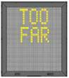 | If the aircraft has overshot the stop-position, ‘TOO FAR’ will be displayed. |
| STOP SHORT | 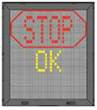 | If the aircraft is found standing still but has not reached the intended stop position, the message ‘STOP, OK’ will be shown after a pre- configured time. |
| AIRCRAFT VERIFICATION FAILURE |  | During entry into the Stand, the aircraft geometry is being checked. If, for any reason, aircraft verification is not made 12 M before the stop-position, the display will first show ‘WAIT’ and make a second verification check. If this fails, ‘STOP’ and ‘ID FAIL’ will be displayed. |
| GATE BLOCKED | 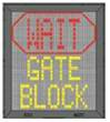 | If an object is found blocking the approach to gate/apron view from the safedock to the planned stop position for the aircraft, the docking procedure will be halted with a ‘WAIT’ and ‘GATE BLOCK’ message. |
Stands S340 and S341 also designated as H1 and H2 respectively for itinerant helicopter operations.
Helicopter parking near stand S324 are only for Aerogulf and Police Airwing and not available for fixed‐wing operations.
| Aircraft pushed back from Stands | Nose‐wheel to be aligned with the CL of Stand |
|---|---|
| S810 – S812 | S810 |
| S440L and S440R facing east | S440L |
2.23.4 Runway visual range
ALPHA: Touchdown
BRAVO: Mid-point
CHARLIE: Stop end
ALPHA : touchdown
BRAVO: STOP end
50 M to 400 M: 25 M
400 M to 800M: 50 M
800 M to 2000 M: 100 M
800 M to 2000 M: 100 M
Note: See GEN 3.5.3.5 for reporting procedures
2.23.5 Reduced Runway Separation Minima (RRSM)
- RWY 12
The preceding landing aircraft has landed and has vacated the runway or has passed a point at least 2400 M from the threshold (abeam TWY W12); and is in motion and will vacate the runway without stopping and/or backtracking.
- RWY 30
The preceding landing aircraft has landed and has vacated the runway or has passed a point at least 2400 M from the threshold (abeam TWY W10); and is in motion and will vacate the runway without stopping and/or backtracking.
- RWY 12
The preceding departing aircraft is, or will be, airborne and has passed a point at least 2400 M from the threshold (abeam TWY W12).
- RWY 30
The preceding departing aircraft is, or will be, airborne and has passed a point at least 2400 M from the threshold (abeam TWY W10).
- RWY 12
The preceding aircraft is airborne and has passed a point at least 2450 M from the threshold (abeam TWY W12) and increasing separation continues to exist between the two aircraft immediately after take-off of the second.
- RWY 30
The preceding aircraft is airborne and has passed a point at least 2400 M from the threshold (abeam TWY W10) and increasing separation continues to exist between the two aircraft immediately after take-off of the second.
- A departing aircraft and a succeeding landing aircraft; or
- Two successive landing aircraft; or
- Two successive departing aircraft.
- Tail wind does not exceed 5 KTS, and there are no reports of wind shear;
- MET visibility shall be equal to or greater than 5 KM and the cloud ceiling shall not be lower than 1000 FT and the Air Traffic Controller is satisfied that the pilot of the following aircraft will be able to observe the relevant traffic clearly and continuously;
- The pilot of the following aircraft is provided with traffic information;
- The runway is dry and there is no evidence that the braking action may be adversely affected;
- The controller is able to assess separation visually or by radar derived information;
- Wake turbulence separation minima shall be applied;
- Minimum separation continues to exist between two departing aircraft immediately after takeoff of the second aircraft.
- Landing Clearance Phraseology
"(Call sign) (traffic information e.g. aircraft type & vacating point), wind (direction (.) / speed (knots)), Runway (number) cleared to land"
"(Call sign) (traffic information e.g. aircraft type departing ahead), wind (direction (.) / speed (knots)), Runway (number) cleared to land"
- Departing Clearance Phraseology
"(Call sign) (traffic information e.g. aircraft type departing ahead), wind (direction (.) /speed (knots)), Runway (number) cleared for take‐off"
2.23.6 Wind Shear Warnings
- On receipt of any report of wind shear, ATC will:
- Immediately relay the report to other aircraft potentially affected;
- Pass the full report to the MET Office; and
- Pass the information to other ATC units that may be affected;
- Wind shear reports that are relayed by to other aircraft will contain as many of the following details as possible:
- Aircraft type that reported the wind shear;
- Description of event (e.g. light/moderate severe, or positive/negative);
- Height/altitude wind shear encountered;
- Phase of flight;
- Runway;
- Time of encounter;
- MET/operational information as received from the reporting pilot;
- Effect on aircraft and/or action taken by the pilot.
- Examples of the phraseology used by ATC to pass on wind shear reports:
- “CAUTION WIND SHEAR. AT (TIME) (AIRCRAFT TYPE) REPORTED STRONG WIND AT (HEIGHT/ALTITUDE) FEET ON APPROACH RWY (DESIGNATOR). MAX THRUST WAS REQUIRED”.
- "CAUTION WIND SHEAR. AT (TIME) (AIRCRAFT TYPE) REPORTED AFTER DEPARTING RUNWAY (DESIGNATOR) AT (HEIGHT/ALTITUDE) FEET AIRSPEED LOSS OF(NUMBER) KNOTS, STRONG (LEFT/RIGHT) DRIFT".
- Wind shear warning issued by NCM or received from an aircraft will be broadcast on the ATIS.
- Regardless of any relevant information being broadcast on the ATIS, during final approach and prior to take-off, ATC will transmit to aircraft without delay:
- The latest information, on wind shear in the approach, final approach, take-off and climb-out area; and
- Any significant variations in the current surface wind, expressed in terms of minimum and maximum values.
- For the benefit of subsequent aircraft and for validation and further enhancement of the low-level wind shear warning, pilots are requested to inform ATC if they experience any wind shear on arrival or departure, irrespective of whether a warning has been given. ATC will pass such reports to following aircraft and the MET Office. Pilot reports should conform to the requirements of ICAO Annex 3, Appendix 4, section 4.1.
- Wind shear reports will continue to be passed by ATC to pilots likely to be affected until it is confirmed, either by subsequent aircraft reports or by advice from the MET Office that conditions are no longer a hazard to the operations.
OMDW AD 2.24 CHARTS RELATED TO AERODROME
